Wednesday, December 11, 2013

Time Lapse Photography, Part 2 - The Basics

As explained in part 1 of this introduction, slow motion and time lapse are effectively opposite premises. Slow motion captures action at an extremely HIGH FRAME RATE, while stop motion in turn captures action occurring at much SLOWER FRAME RATE. If you wanted to capture motion that happens much faster than you can see, you're going to need a faster frame rate. If you want to capture motion that occurs much slower than we can see, then you're going to need a slower frame rate.


Frame rates in the instance of time lapse photography can refer to two things: 1. The rate at which we are capturing images, or 2. The rate at which our images are being played back for an audience.


For example, if we are displaying a video for people to watch, they're most likely going to be watching this video in 24 or 30 frames per second. This is roughly the rate at which the human eye “refreshes”, allowing us to infer smooth motion. When we get into post production of images, and how to compose time lapse images, we will go over frame rates for final processing and how they work. For now, just know that 30 fps is a good rate for people to see motion and make smooth productions.


In the other instance, we use frame rates to explain how frequently we are going to be capturing images. The science behind time lapse can be as specific or as vague as you really want. If you're in a hurry and want to capture a few minutes of some action, you can throw a set up, start your intervalometer and let it run, and you may get a decent result. However, if you're looking to create videos that capture motion appropriately and get you the best results, you're going to want to do some more reading.


Imagine these few different scenarios:
  1. You're laying in the grass watching the clouds roll by while you read a book or have a picnic. The clouds are your focus here.
  2. It's 10pm, its dark out, and you're on top of a building overlooking a city skyline with lots of cars and pedestrians passing in the foreground. The lights are your focus here.
  3. You work in a tall building in NYC, that has a perfect view of the #1 WTC construction. You want to shoot a lapse lasting 10 years.


Now again, for some of these scenarios, you can hook up a cheap intervalometer, press go, and maybe come up with some decent work. But the issue that stands here is that all of these types of motion are going to be take significantly different amounts of time. Let's break down the reasons behind planning for these scenarios.


  1. Clouds move fairly quick. If you're patient, you can sit and watch one move from one end of your vision to the other. Other clouds move much slower, or not at all. Because of this, this kind of motion can be captured within a few minutes. Something like 10 minutes worth of shooting will get you decent results. What's most important though is that you are shooting frames rapidly enough, so that when you put them together they are going to translate the motion.
    So for example, lets say you have 10 minutes to spare and the clouds are moving quick and the scene is just right. As a reference point, I'll just let you know roughly 5 – 6 seconds between shots is an acceptable amount of time for this kind of motion. So, some quick math:
      10 minutes * 60 seconds = 600 seconds
      600 seconds / 6 = 100 frames
      100 frames / 24 fps = roughly 4 seconds of footage.

  1. Ok, scenario 2 begins to get more complicated. Because of it being nighttime, we need to ensure we have a fast enough shutter speed so as to avoid motion blur. The basic laws of photography still stand even though we're shooting lapses. So do your homework and make sure you have everything you need before you run out at night trying to do this. Aside from a fast shutter, we're going to have a very short interval as well. For a scene that involves cars driving by, or pedestrians moving in and out of frame, it would be beneficial to utilize a faster interval. Something along the lines of 3-4 seconds in between shots should help keep the motion smooth and allow the viewer to follow the action.

  1. Finally for this last scenario, we are looking at a much much LONGER interval. If we're doing 10 years worth of action, and progress, we have a lot of factors to consider. First, it would be wise to get an estimate of how often visible progress will actually be made in construction. For something like this, you might look out your window ever single day and never see any visible changes for a week or two. On the other hand, the workers might hit a patch of work that flies by in comparison to something that might take weeks or months, and may produce no visible change. It's a situation such as this that we are going to use an interval probably somewhere in the range of 1x per day or 1x every 2 days. Lets look at the math:

      10 years * 365 a year = 3650 days
      1 shot * 3650 days = 3650 frames
      3650 / 30 fps = 121 seconds = 2 minutes of footage

So, of course, in this instance, for 10 years worth of work, we are going to want longer than a 2 minute clip. At the very least, we're going to want something close to a 5 minute video. Let's figure it out backwards.


5 minutes = 300 seconds
300 * 30 fps = 9000 frames total
9000 / 3650 days = 2.5 shots a day


When you look at it on paper, it's not a difficult concept. But pack all your bags, plan your trip, haul your gear out to location, get set up, and then come to realize you have no calculations prepared, or any idea of how to estimate the shoot, and you'll be kicking yourself. Understand the relationship between frame rates, and how this affects your timing between shots, and you should be able to do the simple math in your head any time. For those of you looking to take all of the guess work out of this, there are a handful of interval calculators available for android and iPhone.


With those examples, you should have a stronger idea of how frame rates play a major part in planning your shoots. With this knowledge, you should also be starting to see the need for tools that most camera's don't come with off the shelf. While some newer digital point and shoots are starting to come with an interval mode, the fact is, most don't have them, and on top of this, any out-of-the-box mode is never going to comparable to a strong understanding of the principles.

In parts 3 & 4 of this project, I'm going to go over my build and share all the things I learned along the way. My ideas weren't perfect, but they were unique and hadn't been attempted before. Some things worked great, while others failed miserably. Regardless, my goal for this project was to save a few bucks and have a working dolly for time lapse projects. In my attempt, I got a working DSLR dolly for roughly half the cost of major distributors. The next two posts will be mostly hardware related, outlining my build including a parts list and a lot of good resources for those of you working on these dolly projects.

For those of you looking for more a in depth code break down, well....we're not there yet. The controller I ended up using was an MX2 dollyengine, which already has a great deal of documentation on it. Dynamic Perception has been great about embracing open source projects, and already gives great insight in to how their product works. Perhaps one day in the future, we'll see what sorts of tinkering we can do with this thing.

Virtual Reality, Nausea, and preparing for the Oculus Rift.

I wrote this post like 6 months ago but neglected to ever post it. Have spent a good amount of time with the Oculus Rift and will do a new post with my thoughts.

The countdown has begun! Technically the countdown started on Jan 16th when I ordered the rift...but after last night it really started when I received the following email: Your Oculus Rift has shipped.


I've been distracted with the news ever since scouring the internet for articles, threads, blogs, subreddits, and websites dedicated to Oculus Rift news and information in an attempt to be completely prepared for when it arrives. Similar to my entries about the Raspberry Pi and other micro computers, I'll be using this blog to chronicle my misadventures.


AN INTRODUCTION

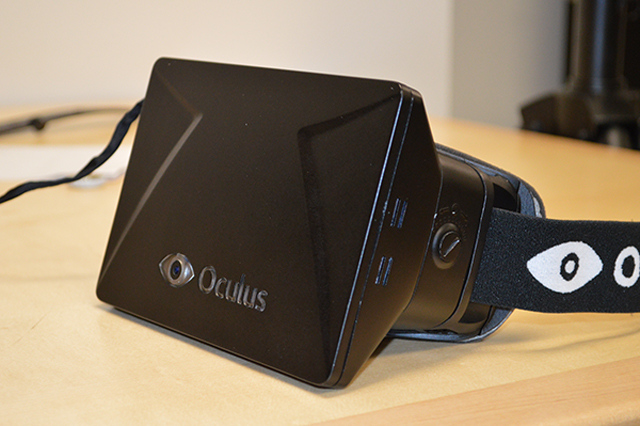
The Oculus Rift is a new hardware peripheral allowing premiere virtual reality experiences at consumer level pricing.  Last year a Kickstarter campaign was started to provide funding for development and manufacturing of the device, they well exceeded their Kickstarter goal and in the past 6 weeks have begun shipping the development version of the product. 

The hardware advancements of today have made a believable virtual reality experience possible for relatively low cost. Mobile phones have really been the forefront of the push for small high density displays, pushing the cost of the parts needed significantly lower. 

RoadToVr is maintaining a well put together page for currently supported and in development games. 

THE FUTURE

I'm excited to explore again in the worlds I discovered years ago.  A...lot...of....people who already received their development kit seem to comment on the sense of scale. You feel how tall (or small) you are supposed to be in the game world. The tunnel vision our brain tries to build for immersion is no longer working harder than necessary. You are there.

below: my roommate trying 'Alone in the Rift'


Some people have experienced sickness from this sensation or a feeling of uneasiness...of your brain making movements your body isn't physically feeling. Imagine rolling in an plane but instead of moving with the plane, your body remains completely still, and just your eyes move. It's a hard concept to visualize and even more difficult to experience.


THE CONSECUTIVE POST

Now that I've had the Oculus Rift for about 5 months I've had some time to reflect. Next post will cover my first time reaction and other reactions I've witnessed. Games that I've played and enjoyed using the Rift and exploring some of my own ideas for using this technology.


Sunday, May 26, 2013

Time Lapse Photography, Part 1 - An Introduction

Photography has been around a long time. The basic ideas and science behind photography hasn't changed significantly unless you consider ideas such as rolling shutters, and the huge amount of small, cheap digital cameras that have popped up in the past 15 or so years.
The basic premise is the same across all formats though, you have a shutter(or a combination thereof), a lens, and a small set of circuitry that opens these shutters, flips mirrors, and times everything down to thousands, or sometimes millions of seconds. 
Film is simply an extrapolation thereof, old film strips are just long lines of images, played at a fast frame rate (24 or 30 fps), or an extremely fast frame rate (1000+) for modern high speed cameras.

Time lapse photography is a method utilized by a variety of filmmakers over generations. Time lapse, and slow motion are effectively opposite ideas. Things that you see in slow motion such as this one are images captured at a rate much FASTER than the human eye can see.

The opposite end of this spectrum is time lapse. Video that produce a time lapsing effect is captured a much SLOWER rate than the eye can see.
Work here property of http://projectyose.com/

Time lapse photography is the focus of our current project and will ultimately be the focus of many future posts regarding such. In the video above, you will notice a motion from the camera where it moves on a plane either on a diagonal, or panning from left to right. It is the production of this motion, in conjunction with telling the camera when to fire, that will be the main focus of this project. 

There are many high end professional camera dollies on the market: 
Many that are used in high end film production and film sets. These cost thousands or tens of thousands and can carry a camera man, and a 200 lb camera. 


There are also small production dollies that carry either a small 1080p camera, a RED camera, or a beefy SLR. 
There are also smaller production dollies made specifically for DSLRs. This is going to be the type of dolly that we are working on. It seems many DSLR owners have already been seeking a cheap solution to adding motion to their work, so as such a great community of photographers has already formed, many of whom are extra supportive of open source projects and often support reproductions, and sharing of ideas. One resource that immediately shows it's wealth is http://openmoco.org/ This community of photographers, programmers and problems solvers have been sharing ideas for years and many of them have started their own businesses providing motion control to other photographers. 

In part 2 of this introduction I will further explain the mechanics behind time lapse, motion control, and how the two come together to make great video compositions. In the posts following this, we will be building a motion controlled camera dolly to carry a DSLR. To build it, we're going to use many open source parts, both hardware, and software wise. The heart of the project contains an Arduino, an LCD shield, motor shield, and camera controller. As such, all of the programming is almost entirely going to be related to the Arduino. 

If you're interested in more reading, check out openmoco.org, or for more videos http://timescapes.org/

If you're interested in purchasing a ready-built dolly, that you can hook up to a DSLR camera and go, then I can't recommend a company any higher than dynamicperception.com. Dynamic Perception highly supports open source design, and is a major inspiration for the build that follows. They make amazing products that is backed up by amazing customer support. For those of us that like to tinker though, stay tuned! We're going to go over a variety of options and things to consider when building your own dolly. 

Tuesday, April 23, 2013

.NET, OAuth2, and the Google Analytics Service account.

Google likes to change things. About a year ago I went through one of their C#  Data Export examples to grab some Analytics data for a program I was writing. The previous method of authentication was easy add the user/pass into the url request or add an API key to the query.

In August 2012 Google deprecated the v2.3 reporting and authentication method in favor of OAuth2 at the time of deprecation Google didn't provide a lot of information for C# / .NET developers who needed to migrate off the old way.

http://code.google.com/p/gdata-issues/issues/detail?id=2955

Since that time they've improved their dot-net-client libraries and wrote a tutorial on authenticating with OAuth2. I wasn't able to get their code to compile when I attempted but it did put me on the correct path.

This is a project of firsts: first time with MVC, first time attempting to make a SPA (Single-Page Application) Knockout.js, and first time working with OAuth2 authentication.  I followed John Papa's excellent SPA Overview for the most part.

The latest WebSite and MVC WebSite default templates from Microsoft have OAuth2 authentication built in and doesn't require any setup at all just two-step authentication with whatever service we're logging in with.
I didn't want this since I only wanted access to my analytics account. The analytics API also seemed to have some issues getting certain information using this method.

After some intense googling I found the OAuth2 Service account of course with no working C#/.NET examples...This is what I ended up doing.

I put everything I could find together into this project.

Follow the beginning of Googles OAuth2  tutorial and register your app in Googles API Console.

Create a ClientID and choose 'service account' download your private key.  


Edit the following:

Models/Utils.cs

 public static IAuthenticator getCredentials(string scope)
    {
        const string ServiceAccountId = "SERVICEACCOUNTID.apps.googleusercontent.com";
        const string ServiceAccountUser = "ServiceAccountUser@developer.gserviceaccount.com";
      try
      {
          AssertionFlowClient client = new AssertionFlowClient(
              GoogleAuthenticationServer.Description,
              new X509Certificate2(
                  HttpContext.Current.Server.MapPath("~/Content/key/0eee0d919aaef70bbb5da23b192aede576577058-privatekey.p12"), "notasecret", X509KeyStorageFlags.Exportable))
{ Scope = scope,  ServiceAccountId = ServiceAccountUser};
 OAuth2Authenticator<AssertionFlowClient> authenticator = new OAuth2Authenticator<AssertionFlowClient>(client, AssertionFlowClient.GetState);
 return authenticator;
}
catch (Exception ex)
{ }
 return null;
}
Changing the path to the location of the key download from the console earlier. and changing SERVICEACCOUNTID and ServiceAccountUser to whats listed in the API Console. Once thats completed the Controller will attempt to authenticate using the method below:
try {
    Session["authenticator"] = Utils.getCredentials(AnalyticsService.Scopes.AnalyticsReadonly.GetStringValue());
    IAuthenticator authenticator = Session["authenticator"] as IAuthenticator;
    AnalyticsService service = new AnalyticsService(new BaseClientService.Initializer() {
        Authenticator = authenticator
    });
    var profiles = service.Management.Profiles.List("~all", "~all").Fetch();
    user.profiles = profiles;

} catch (Exception ex) {
    ViewBag.Error = ex.Message;
    return View("Error");
}
One thing to note is that it seems this current version can only authenticate one scope at a time...I've been unable to pass in more than one.

AnalyticsService.Scopes.AnalyticsReadonly.GetStringValue() will only bring back the profiles that are available under the authenticated account.

A different scope is needed to query the profiles and the analytics data in them. In addition to changing the scope the service account  needs to be added to the analytics profile as an authenticated user.

GitHub Project
Google Dot Net Client Libraries
Google OAuth2 
Google Service Account documentation 

Saturday, April 13, 2013

RaspberryPi, Boblight, and the WS2801 LED - Follow up


(game isn't using boblight leds)

Had some time this weekend to follow up on some of the comments from my last post.

Gregory posted a link to this excellent tutorial. Allowing boblight and xbmc to run off the same pi.

cell phone camera doesn't capture the colors correctly but you get the idea:


Tuesday, March 5, 2013

RaspberryPi, Boblight, and the WS2801 LED - Part 3


Part 1 of my blog series went over our parts list and initial setup for this project. 

Part 2 dived into a little bit of code and making those LEDS light up for the first time.

This final part will go over installing Boblightd, XBMC boblight add-on,  mounting the LEDS and configuring them to look their best. 

If you followed Part 1 and Part 2, you should know how to SSH into the raspberry pi. Make note of your raspberry pi IP Address we'll be using it soon.  Once logged in run the following commands to install boblight. 

copied from here.

3. Install subversion
  $ sudo apt-get install subversion
4. Clone boblight source
  $ cd ~
  $ svn checkout http://boblight.googlecode.com/svn/trunk/ boblight-read-only
5. Compile:
  $ cd boblight-read-only/
  $ ./configure --without-portaudio --without-x11 --without-libusb 
If everything goes well.....
  $ make
  $ sudo make install
6. now configure your setup, see conf/LPD8806.conf for examples and move .conf file to /etc/boblight.conf
  $ sudo cp conf/LPD8806.conf /etc/boblight.conf
7. you can test now by starting boblightd
  $ sudo boblightd
we have to run boblightd using sudo for SPI to work
8. if you like, you can add boblightd to /etc/rc.local for it to start on boot
  $ sudo nano /etc/rc.local
and add
  /usr/local/bin/boblightd -f
before exit

Once Boblight is installed open up XBMC and go to 
  1. Settings
  2. Add-ons
  3. Get add-ons
  4. XBMC.org Add-ons
  5. Services
  6. XBMC Boblight
  7. Install

At this point you should be able to configure the boblight addon on XBMC. If you open the addon settings it should ask for an ip address. Type in your raspberry pi ip and hit ok.   If you restart XBMC and everything went correctly...the LEDS will light up RED, GREEN, BLUE and either turn off or go to the ambient color configured in the settings. 

We're almost there! We still need to configure boblightd for the amount and orientation of theLEDS. You can do this manually or you can use a program somebody wrote for this purpose. 


This will spit out our boblight.conf file. You'll need to edit this before copying to the raspberry pi.

Boblight is normally used with an arduino connected by usb so thats the output/interface by default you should just need to change the output and the interface.

/dev/spidev0.0 is the output needed for the pi to communicate with the LEDS
The interface needs to be changed to the raspberry pis ip address.

The beginning of my boblight.conf:
[global]
interface  192.168.1.13
port      19333
[device]
name            ambilight
type            momo
output          /dev/spidev0.0
channels        150
interval        20000
rate            115200
debug           off


This was kind of a pain to copy to the raspberry pi. Especially through command line.

Easiest way I found is to COPY the entire boblight.conf and create a new file

 sudo nano boblightd.conf


 and then PASTE the config into it. 

and finally copy that file over your boblight.conf file

sudo cp boblightd.conf /etc/boblight.conf


Thats it! If everything went well boblight shoudl be configured. Every time you start up XBMC on your pc it should look for the the raspberry pi ip address and connect.
Mounting the LEDS


The picture above is my preliminary OMG I NEED THESE LEDS ON MY TV NOW. I just stuck them on there with some painters tape. Worked for a bit until the tv heated up and melted the sticky. 

Once I got them stickied on there I created a test video for XBMC to play. I just went into mspaint and created a quick picture w/ a different color on each side and rendered that as an avi in Windows Movie Maker. Took about 15mins but it helped significantly when determining the leds were in the correct position. 

In the picture below you can see my monitor in the background corresponding with the LED Colors around the tv. 


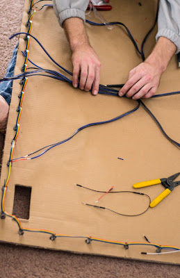
Once we figured out how the LEDS were going to be laid out I cut up my TV Box for a large chunk of cardboard.

I've seen some much better implementations for an LED mount but i'm cheap and lazy.


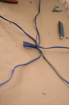
This picture and the one below show our power distribution for the LEDS something we probably didn't need to do with the amount of LEDS that we used (50). We noticed some drop off in brightness so we decided to do it anyways. 


Notes: I'm still working on this project. Right now I have two Raspberry pis one to control the LEDS and one to run XBMC...unfortunately I haven't had the time to go through some of the forum posts regarding RaspBMC + Boblight addon. It seems somebody out there has gotten XBMC on the raspberry pi to talk with boblight using omxplayer. I'll do a follow up post once I figure it out and get it workin. For right now using my windows pc connected to the TV works out great. 


Wednesday, February 20, 2013

RaspberryPi, Boblight, and the WS2801 LED - Part 2


For the most part this tutorial follows the instructions outlined here.  
This is part 2 of my Raspberry Pi and WS2801 LED post. Part one went over the preparation and parts needed to make the LEDS and Raspberry Pi talk to each other. Part 2 will focus on putting everything together and capitalizing on  that communication.

We used a breadboard when we were prototyping the power and data connections between the RaspberryPi  and the LEDS. According to the diagram below our power is coming from an external 5V source (not from the RaspberryPis  micro usb) this is needed to properly power the LEDS.


I did a lot of scavenging and found a 5v 3amp power supply for the LEDS and the RaspberryPi. We actually had some success powering the RaspberryPi and the LEDS through USB but found that the last LEDS in the strand were a bit dimmer. In the final build we distributed the power every 10 LEDS but i'll discuss that in a later post. 

The power supply is connected into this which is then connected to the breadboard via jumper cables.
The pictures below are from our initial setup.


raspberry pi ws2801 power
We didn't use the breadboard in our final version, it was just an easy way of distributing the power and data connections without stripping cables. 

Once the LEDS are connected it's time to run some software to see if everything works correctly. 
If you followed part one of this tutorial you should have the Adafruit WebIDE installed and running at this point. We'll use this to test our LEDS. 

I had some trouble with the local name that the you're supposed to be able to access the IDE from . 
http://raspberrypi.local:3000 according to the tutorial. My local network couldn't resolve the name, but it had no trouble accessing the IDE via IP. So navigate your browser to http://YOUR-RPi-IPADDRESS:3000

If all went well you'll be greeted with this page:


The IDE requires you to sign up for a BitBucket account. Which will privately hold your code (unless you want it public) in their cloud. This worked out pretty well for me since i had to install the WebIDE a few times for it to work correctly. I wrote some custom scripts which were saved between installs on my BitBucket account. 

Once signed in navigate through the examples to Adafruit_LEDPixels.py:


The arrow in the picture point out:

SPICLK = 18
SPIDO = 17

These are the pins that the Pi is going to send data to when this python script is run.
This post here explains why were using these pins on the RaspberryPi. 

If everything looks like its in the right spot hit the 'Run' button up top. If it worked you'll see the LEDS light up RED, GREEN,  BLUE, then cycle through a spectrum of colors. 

I sat and screwed around with the python scripts for a bit once I hit this point. With some fairly simple changes you can do some cool stuff with the LEDS from this point. Heres a quick script I wrote to check your gmail for the subject ALARM.


 #!/usr/bin/env python  

 import RPi.GPIO as GPIO, feedparser, time  

 import thread  

 DEBUG = 1  

 SPICLK = 18  

 SPIDO = 17  

 ledpixels = [0] * 40  

 GPIO.setmode(GPIO.BCM)  

 USERNAME = "GMAILUSER"    

 PASSWORD = "GMAILPASS"     

 NEWMAIL_OFFSET = 1      

 MAIL_CHECK_FREQ = 60   

 def Color(r, g, b):  

      return ((r & 0xFF) << 16) | ((g & 0xFF) << 8) | (b & 0xFF)  

 #Colors  

 RED = Color(255, 0, 0)  

 BLUE = Color(0, 0, 255)  

 GREEN = Color(0, 255, 0)  

 ORANGE = Color(177, 53, 47)  

 OFF = Color(0, 0, 0)  

 colors = []  

 allfalse = False  

 def writestrip(pixels):  

      spidev = file("/dev/spidev0.0", "w")  

      for i in range(len(pixels)):  

           spidev.write(chr((pixels[i]>>16) & 0xFF))  

           spidev.write(chr((pixels[i]>>8) & 0xFF))  

           spidev.write(chr(pixels[i] & 0xFF))  

      spidev.close()  

      #time.sleep(0.002)  

 def setpixelcolor(pixels, n, c):  

      if (n >= len(pixels)):  

           return  

      pixels[n] = c  

 def alert(color, delay):                                                                                                                                                                                                                                                                                                                                                                                                                                                                                                                                  

      for i in range(len(ledpixels)):  

           setpixelcolor(ledpixels, i, color)  

           writestrip(ledpixels)  

      time.sleep(delay)       

 def multiColor(colors):  

      b = 0  

      for i in range(len(ledpixels)):  

           setpixelcolor(ledpixels, i, colors[b])  

           writestrip(ledpixels)  

           time.sleep(delay)  

           b = b + 1  

           if(b >= len(colors)):  

                b = 0  

 def loopColors(status, colors):  

      if(status == True):  

           print("new thread")  

           for a in range(len(colors)):  

                alert(colors[a], .5)  

                time.sleep(.5)  

      else:  

           alert(OFF,5)  

 class Emailees:  

      def __init__(self, email, hasEmail, color):  

           self.email = email  

           self.hasEmail = hasEmail  

           self.color = color  

 def emailAlarmCheck(delay):  

      allmails = feedparser.parse("https://" + USERNAME + ":" + PASSWORD +"@mail.google.com/gmail/feed/atom")  

      alarm = Emailees("ALARM", False, RED)  

      for i in range(len(allmails.entries)):  

           if(allmails.entries[i].title == alarm.email):  

                alarm.hasEmail = True  

                colors.append(RED)  

                print("Found ALARM")  

      allfalse = [alarm.hasEmail]  

      loopColors(allfalse, colors)  

      print(len(allmails.entries))  

      time.sleep(1)  

 while True:  

      emailAlarmCheck(.5)       

  ##  


Congratulations! If you made it this far you're only one step away from playing your movies with dynamic LEDS. My next and final part will cover Boblight, XBMC addons, Adalight, and attaching your lights to some sort of structure.


Monday, February 4, 2013

RaspberryPi, Boblight, and the WS2801 LED


raspberry pi ws2801 breadboard configuration taken in the midst of testing a bunch of things. it's a lot more cleaned up now.

A couple months ago I was looking for a project to start for my new Raspberry Pi. As soon as I saw the video after the jump I knew what had to be done.


Backlights! for your TV. This experience is only offered on some pricey high end phillips tvs that don't seem to be available in America., it's also available to us tinkerers for less than $125.

I'm currently on Windows 8, so if you're running Linux or Mac you'll need to substitute certain programs out like PuTTY for SSH.


Software:


Hardware:

  • WS2801 LED Strand (50pc) or more
  • 5-Port Switch
  • 5v 3amp(min) DC Power Supply
  • 4Gb Class 10 SD Card
  • Raspberry Pi
  • Breadboard
  • Male to Female .1" 2.43'mm Jumper Cables 
  • Wire Cutters
  • Electrical Tape
  • Zip Ties
  • Multimeter 
  • (optional) 5v MicroUSB Power
  • (optional) HDMI to VGA adapter


Download the latest image of Occidentalis and install it onto our Raspberry Pi. This OS doesn't necessarily need to be used but it will make things easier. With this image the Pi can be powered on by the GPIO pins, which will be required later, it also contains some of the packages required by boblight to communicate with those pins.


Connect the Ethernet Cable, SD Card, and lastly the MicroUSB power to the Pi.
If the OS was installed correctly this should start the boot process.

NOTE: This is a headless OS. Meaning there is no GUI by default. Our intention is to turn the machine on and "use it" over the network from your main PC. There will be no monitors or TVs attached to the raspberry pi driving the lights. 


Once Occidentalis is installed we'll need to SSH into the Pi and configure it. (Assuming you're connected to the network via ethernet)

This can be done fairly easily if you have a keyboard connected to the Pi log in with the default login. Otherwise I will usually logon to my router to check connected devices.

User: pi
Password: raspberry

ifconfig

you'll notice inet addr: 192.168.1.13
this is your Pi's IP Address.


If we open up PuTTY we'll be able to connect to the address above.


I've made it a habit to immediately run updates/upgrades

sudo apt-get install update
sudo apt-get install upgrade

Our next step is installing the adafruit Raspberry Pi WebIDE
paste the following command:

curl https://raw.github.com/adafruit/Adafruit-WebIDE/alpha/scripts/install.sh | sudo sh

Go grab a beer and wait for the install script to finish.


Once completed you'll be able to access http://raspberrypi.local and your Raspberry Pi is now fully prepared to program LEDS from a browser!

In Part 2 we'll talk about power distribution, light painting, breadboards, and we'll connect those LEDS!